
Ishikawa Diagram: Origin, Evolution, and Application in Continuous Improvement
Abstract
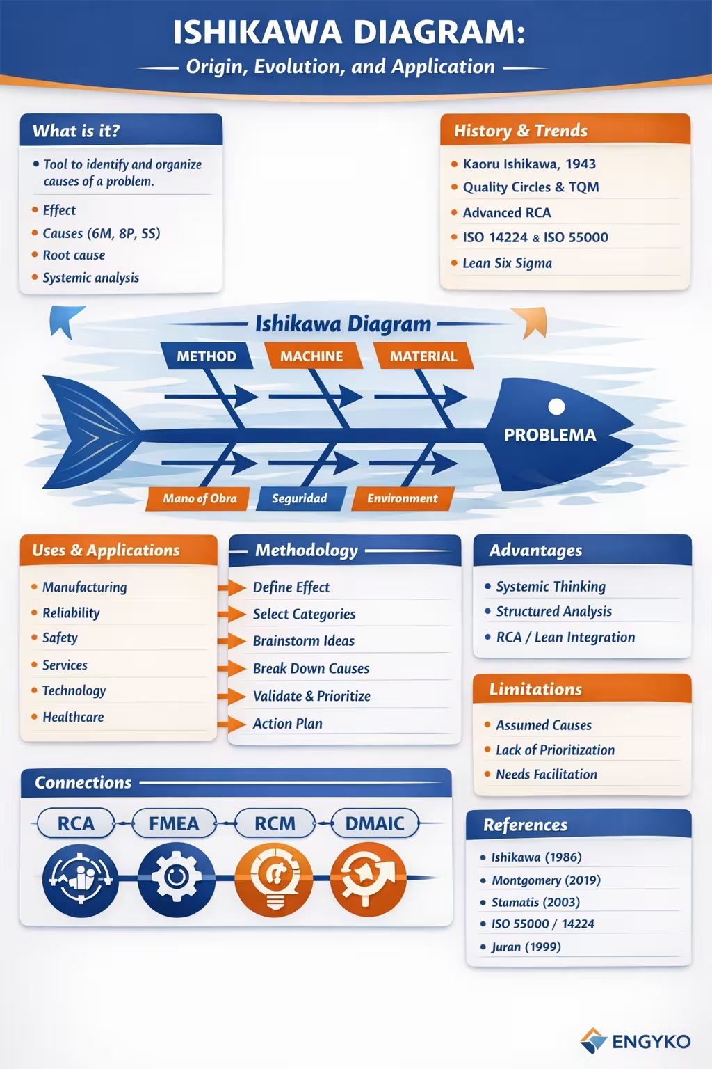
The Ishikawa Diagram, also known as the Cause‑and‑Effect Diagram or Fishbone Diagram, is one of the most influential tools in quality management, reliability engineering, and structured problem solving. Its purpose is to identify, organize, and visualize potential causes that lead to a problem, enabling deep analysis and evidence‑based decision‑making.
1. What Is the Ishikawa Diagram?
The Ishikawa Diagram is a graphical tool that represents the relationship between an effect (problem, deviation, failure) and its potential causes, grouped into logical categories. Its distinctive “fishbone” shape promotes systemic thinking and visual clarity.
It is used to:
- Identify root causes
- Organize information during analysis sessions
- Facilitate multidisciplinary discussions
- Standardize critical thinking in improvement processes
2. History and Evolution
The diagram was created in 1943 by Kaoru Ishikawa, a Japanese chemical engineer and pioneer of total quality management. His goal was to help manufacturing teams identify sources of variability.
Historical Milestones
- 1950s: Adopted by Japanese Quality Control Circles
- 1960s: Became one of the Seven Basic Tools of Quality
- 1980s: Global adoption during the rise of TQM and Japanese manufacturing
- 21st century: Expanded into reliability, safety, services, IT, healthcare, and complex failure analysis
Current Trends
- Integration with advanced RCA (Apollo, TapRooT, PROACT)
- Use in asset failure analysis aligned with ISO 14224 and ISO 55000
- Key role in Lean Six Sigma (DMAIC analysis phase)
- Digitalization through collaborative software and AI‑assisted analytics
- Adaptation to Agile and DevOps environments for incident analysis
3. Uses and Fields of Application
The Ishikawa Diagram is cross‑industry and widely applicable:
Manufacturing and Process Engineering
- Production variability
- Quality defects
- Unplanned shutdowns
Reliability and Maintenance
- Failure analysis
- Pre‑FMEA mode identification
- RCM integration
Safety and Risk Management
- Incident investigation
- Identification of latent causes
Services and Logistics
- Delays and inefficiencies
- Administrative errors
- Customer service issues
Technology and Software
- Operational incidents
- Recurring bugs
- Performance problems
Healthcare
- Adverse events
- Medication errors
- Clinical process failures
4. Methodology for Building an Ishikawa Diagram
Step 1: Define the Effect
Clearly state the problem in measurable, verifiable terms.
Example: “High failure rate in centrifugal pumps model X.”
Step 2: Select Cause Categories
Common frameworks include:
- 6M (Manufacturing): Manpower, Method, Machine, Material, Measurement, Environment
- 8P (Services): People, Process, Policies, Place, Procedures, Price, Promotion, Product
- 5S (IT): Software, Systems, Skills, Suppliers, Security
Step 3: Structured Brainstorming
Identify potential causes within each category using:
- Guided brainstorming
- 5 Whys technique
- Historical data analysis
- Field evidence
Step 4: Hierarchical Breakdown
Decompose each cause into sub‑causes until reaching actionable levels.
Step 5: Validation
Confirm causes through:
- Data analysis
- Inspections
- Testing
- Documentation review
Step 6: Prioritization
Apply tools such as:
- Impact matrices
- Pareto analysis
- Risk assessment
Step 7: Action Plan
Translate validated causes into corrective and preventive actions.
5. Advantages
- Encourages systemic thinking
- Facilitates multidisciplinary collaboration
- Structures cause analysis
- Simple, visual, and universal
- Integrates seamlessly with RCA, FMEA, RCM, Lean, and Six Sigma
6. Limitations
- Does not automatically distinguish real from assumed causes
- May produce extensive lists without prioritization
- Requires skilled facilitation to avoid bias
- Cannot replace quantitative analysis
7. Connection with Other Methodologies
The Ishikawa Diagram integrates naturally with:
- RCA — initial exploration tool
- FMEA/FMECA — failure mode identification
- RCM — functional cause mapping
- DMAIC — analysis phase
- ISO 9001, ISO 14224, ISO 55000 — quality and asset management frameworks
8. Conclusion
The Ishikawa Diagram remains a cornerstone of modern engineering, reliability, and continuous improvement. Its simplicity and analytical power make it indispensable for organizations pursuing operational excellence and evidence‑based decision‑making.
9. References
(APA format, publication‑ready)
- Ishikawa, K. (1986). Guide to Quality Control. Asian Productivity Organization.
- Montgomery, D. (2019). Introduction to Statistical Quality Control. Wiley.
- Stamatis, D. (2003). Failure Mode and Effect Analysis. ASQ Quality Press.
- Benbow, D., & Kubiak, T. (2018). The Certified Six Sigma Black Belt Handbook. ASQ.
- Moubray, J. (1997). Reliability‑Centered Maintenance. Industrial Press.
- IEC. (2016). IEC 60300 – Dependability Management. International Electrotechnical Commission.
- ISO. (2014). ISO 55000 – Asset Management. International Organization for Standardization.
- Juran, J. (1999). Juran’s Quality Handbook. McGraw‑Hill.
Comments